

Disclaimer: Opinions shared in this, and all my posts are mine, and mine alone. They do not reflect the views of my employer(s) and are not investment advice.
Most content in computer architecture courses, and also my newsletter, focus on how a computing chip “computes” - by exploring how the processor core, memory, I/O, and other parts of the chip work in isolation. But in reality, a large portion of time and energy consumed by computing chips is a result of the interactions between the different components of the chip. (called “nodes.”) For instance, moving data from memory and I/O to and from the processor core, or moving data between processor cores. For a long time, these have been assumed to be trivial. (and in reality, they were.) But with increasing number of cores and deeper memory hierarchies, efficiently moving data across a chip can make a huge difference to the overall chip performance. This post intends to introduce the concept to absolute beginners. (If you have been reading my newsletter long enough, you should sense an analogy coming…)
Welcome to your new venture - an airline company
The logistics of airlines has always fascinated me - so that’s the vehicle (pun intended) we are going to use to understand on-chip networks. Imagine this: you read all my posts, became a semiconductor legend, made a lot of money, and have now purchased two Airbus A320 planes, and started a new airline company. Your first task is to decide which routes your airline should operate between, and the logistics behind making this happen. Turns out, designing an on-chip network is surprisingly similar…
Going forward in this post, you can consider the following terms to be analogous:
An airport is similar to a node in the chip (could be a processor core, memory, or I/O component)
An airline route can be treated like a chip bus (bus here is not the transport kind, you can think of it as a collection of wires that can transfer high/low voltage.)
Model 1: Point to point connection
If you have two planes, what’s the simplest thing you can do? You can have two exclusive routes that can operate independently, and in parallel - say one route between Los Angeles (LAX) and San Francisco (SFO), and the other between LAX and New York. (JFK.)
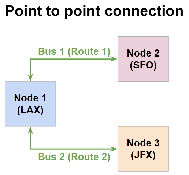
Different nodes in a chip can also be connected in the same way - just have a bus connecting different components with each other, and transfer data through these buses. This is called a “bus-based architecture” and although it seems simple, it is one of the most commonly used networking architecture. (Remember, most airlines continue to operate all-year daily flights between two fixed locations - the logistics can’t be simpler than this.) However, this approach comes with it’s limitations, like:
1. Poor scalability
If you want to increase the number of nodes, you need to increase the number of buses. This makes placement and routing very challenging in the chip. (Do you really want to buy a new plane for each new destination you want to serve?)
2. Limited Flexibility
Having one bus assigned for each connection makes the design very inflexible: Say during execution, two nodes in your chip need to transfer more data than two other nodes, they both still have similar buses with the same bandwidth. It’s like operating an empty flight from LAX to JFK, even though the LAX-SFO route is overbooked!
As you might imagine, the flexibility problem isn’t too hard to solve - you own the airline, so you can be flexible with the routes. That’s the idea of arbitration.
Model 2: Arbitration
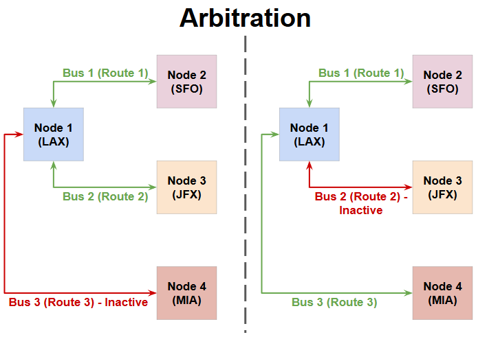
Let’s say you want to add a new destination for your Airline to serve - Miami. (MIA.) However, unlike SFO and JFK, travel to Miami is seasonal, peaking during the holidays. In this case, instead of buying a new plane to serve this route, wouldn’t it make more sense to redirect your flights based on the demand? You can “arbitrate” by:
Operating flights from LAX to SFO and JFK during the week
Changing one, or both of the routes to LAX-MIA during the weekends or major holidays
This idea of arbitration can also be used in chips to connect more nodes without adding new buses - by sharing existing buses. Arbitration can be done in many different ways (called arbitration policies) each with it’s pros and cons. While I’m not going to cover all of them in detail, here are some examples:
Round robin arbitration: Every node gets a turn to use the bus, and then waits for all other nodes to be done before using the bus again.
Daisy chain arbitration: All nodes can access the bus simultaneously, but there is a predefined priority order. (Something like this: If both SFO and MIA are in demand, always pick SFO)
Collision-based arbitration: These are more advanced, and rely on real time chip behavior. (For example: If there are no bookings for next week’s flights to JFX, cancel them and open bookings to MIA.)
As you can guess, arbitration adds complexity to your chip. (In case of your airline company, you can think of this like hiring someone to manage the routes.) But in some cases, arbitration is a great way to reduce the number of buses in the chip - Say you have two cores connected to a memory, but your chip mostly runs tasks on one of the cores - then the bus between the two cores and the memory can be shared.) However, as your chip becomes complex, the shortcomings of arbitration become evident:
1. Bandwidth is limited
Remember, although we are able to serve three destinations now by arbitrating between two planes, we can still only serve two destinations at a time. Let’s say each flight can hold 150 passengers, the maximum number of unique passengers you can transport each day is 300 each way - which is the same as it would be if you operated as a point-to-point connection. In chip language, the maximum amount of data that can be moved from one node to another at a given time is called the bandwidth. Although arbitration will help manage multiple nodes, the bandwidth is still limited by the number of buses in a bus-based architecture.
2. Single point of failure
Arbitration has another issue. Say you have decided to fly one of your planes from LAX to SFO and back on a Friday, but from LAX to MIA on Saturday. (And the other plane is going to JFK both days.) However, thunderstorms hit SFO on Friday, grounding all flights. This means the flight won’t be back to LAX in time for the trip to MIA. So this flight becomes a single point of failure for two of your routes. While the weather does not affect electrons in your chip, failures of other types are possible - say you are using a round-robin arbiter, but one of your core runs into an infinite loop - that core does not release the bus and stops the entire chip from executing. That’s the risk with arbitration-based approaches.
Model 3: The crossbar, a.k.a hub and spoke model
If you have ever flown in one of the major international airlines like Emirates or Qatar airways, you would have experienced a layover at one of their “hubs” like Dubai or Doha. These airlines operate based on a very popular airline routing model called the hub and spoke model. (Inspired from it’s resemblance to your bicycle wheel.) Now that you are a seasoned manager of an airline, let’s take inspiration from this model and add a fourth destination to our airline - Seattle. (SEA.) However this time, the flight schedules are adjusted in such a way that LAX becomes the hub:
Two flights leave each morning from SFO and SEA, respectively, and land in LAX at 11 AM
The same two flights depart from LAX at 3 PM - one to JFK, and the other to MIA
With this model, the airline can sell tickets for the following routes:
SFO-LAX, SEA-LAX, LAX-JFX, LAX-MIA with no layover
SFO-JFK, SEA-JFK, SFO-MIA, SEA-MIA with a layover at LAX
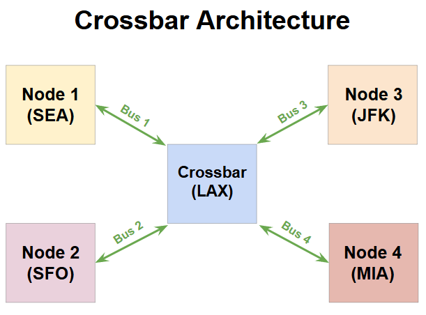
As you can see, LAX is the key to making this happen - it’s where the “crossover” of incoming and outgoing passengers happens. In chip networking, we use a similar arrangement called a crossbar. A crossbar is a collection of programmable switches which can decide which inputs need to be routed to which outputs. (Your airline’s staff in LAX will do this check at the boarding gate.) This allows multiple different nodes in the chip to communicate with each other without the need for direct connections between all the nodes.
Crossbars effectively address both the shortcomings that we saw with arbitration. First, they are able to ensure that all nodes can communicate with each other simultaneously. (The crossbar is assumed to have an ability to monitor these transactions and handle them correctly.) In our airplane example with a hub, we are theoretically able to transport 600 unique passengers in a day. (300 in the morning from SEA/SFO to LAX, and 300 later to JFK/MIA.) Also, the presence of a crossbar means that each failure is restricted to it’s own node - if one of the cores in the chip hit’s an infinite loop, the other cores can still talk to the other nodes through the crossbar.
At first glance, you might think that a crossbar arrangement is very similar to a point to point connection since both cases ensure all nodes can be connected simultaneously. But there’s a subtle difference here - using a crossbar, we are able to achieve the same bandwidth as point-to-point connection, but with fewer bus connections. If a chip has N nodes, (N > 2.) then:
Point-to-point connection would need (N-1)*(N-2) buses
Crossbar connection needs N buses
This is the main advantage of a crossbar. However, in order to maintain the full bandwidth, crossbars usually need to store transactions and have complex control mechanisms, which makes the crossbar an additional piece of silicon taking up area and consuming power. Also, crossbars cannot scale indefinitely - each additional node adds some wire latency, and a very large number of nodes could make this intolerable. Remember, if you have 10 nodes in a crossbar, they all contribute to the wire latency - even if you only use a few nodes repeatedly. Transistor scaling also cannot be relied on - reduction in wire latency has not kept up with Moore’s law, which makes the future of crossbars very uncertain. Basically, as your airline business scales to multiple destinations, you need to hire a lot of staff, and reserve many boarding gates - even on days with low occupancy on your flights. Not ideal…
All of the approaches discussed so far were sufficient for the pre-SoC era: with a small core count, and few memory and I/O nodes that needed networking. But as we entered the era of parallel compute with SoCs having more than a thousand cores, interconnects needed to get more sophisticated. A “Southwest Airlines” moment was needed…
Model 4: The “Network”
In 1971, Southwest airlines launched their first flights in Texas - changing the aviation business model forever. Let’s learn from their approach and make our airlines more efficient.
Despite everything we discussed so far, the truth is, point-to-point non-stop flights are the most desirable options. So let’s go back to our first model, and see if we can take it in a different “direction”. (Pun intended.) I mentioned that one of the issues with point to point connections is the flexibility - how can you best manage different bandwidth requirements on each route? We looked at arbitration in model 2, but there is a more efficient approach - operate smaller flights. Smaller flights are cheaper to fly, and easier to sell-out, hence giving you more bang for buck on each route without the need to arbitrate.
The other limitation was the “buy a new flight for each new route” requirement that point-to-point connections require. Smaller flights will also partially address this issue, because you can afford to buy more flights. (and hence operate more routes simultaneously.) But as you expand your destinations, this might still become impractical - so we will remove this requirement from the model, making it pseudo-point-to-point. (i.e. not all connections can be point-to-point, as you will see.)
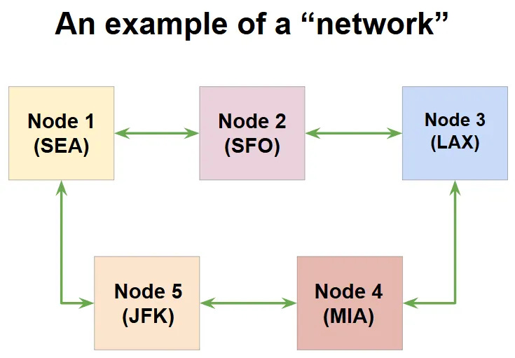
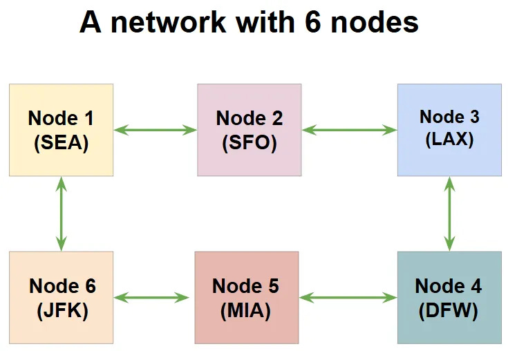
Let’s incorporate all this flexibility and build a network for our 5 destinations that looks like a ring. Much like the crossbar model, this topology connects all our destinations. (using as few as one flight!)
Point-to-point connections: SEA-SFO, SFO-LAX, LAX-MIA, MIA-JFK, JFK-SEA
Pseudo point-to-point connections (with 1 stop): SEA-LAX, SFO-MIA, LAX-JFK, MIA-SEA, JFK-SFO
Adding a destination to this model is trivial. Say you want to add a new destination, Dallas (DFW), in the same topology, you can add the node like this:
Unlike the crossbar architecture, which adds a strain (more staff, larger number of boarding gates, and so on.) on your “hub” for each new destination, this ring-style approach does not stress any single node. (Remember, in chip terms, this “stress” means wire latency.) However, you might already see a problem here - we have introduced connections with 2 stops which would never exist in a crossbar model. (For example, SFO-MIA.) If such 2-stop routes are undesirable, then a simple connection above can fix that - add a direct route between SFO and MIA.
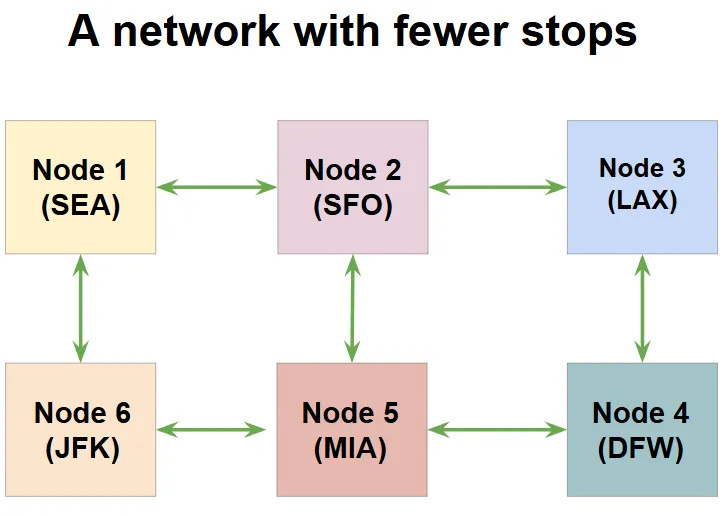
With just one new route, we are able to maintain access all our destinations with one stop or lower. Also, you can pick between one large flight, or multiple small flights - the network can be adjusted accordingly. This is the biggest advantage of the network model - it allows the flexibility to modify the topology based on your resources and latency requirements. Such networks exist in all modern chips, and they are called, simply, a Network on Chip, or NoC. We will look at them more formally in the next section.
An overview of Network on Chip (NoC) architectures
In the previous section, I (hopefully) convinced you that an NoC architecture allows you to move data efficiently and provide maximum flexibility on chips with a large number of nodes. With great flexibility, comes great challenge - and in this section, I want to walk you through three architecture decisions that need to be made, and the trade-offs involved.
1. What should my network look like?
As you saw from the airline analogy, changing which nodes are connected to each other makes a huge difference to the path that needs to be taken to go from one node to the other. In NoC language, each such connection is called a “Link.” By changing the number of links, and the nodes they connect, we get different “Topologies.” We use two key metrics to understand how good a topology is:
Path diversity: How many unique paths can you find between two nodes in your network (formally called “Bisectional Bandwidth,” which I think raises more questions than provides answers, so I won’t use that term.)
Path distance: The maximum distance between any two nodes in the network. (Again, the formal term is “Diameter”; I’m not going to use that.)
As you might expect, adding additional links would increase path diversity, and reduce the path distance. But each link adds hardware complexity. (More wires, and as we will see later, complex routers.) Here’s an example with three simple topologies that highlights this trade-off.
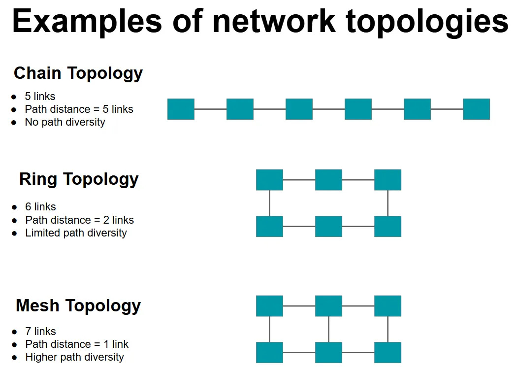
There are more nuances in designing the best topology, but for now, all you need to take away from this section is: Pick a topology that provides sufficient path diversity with the smallest number of links, while also ensuring that your path distance isn’t too much.
2. How do I split up my data?
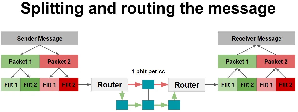
It might seem like ages ago, but if you remember from the start of this post, the purpose of on-chip networks is to move data from one point in a chip to another. Due to the complexity of NoC architectures, we have a dedicated unit in each node to manage the sending and receiving of this data - called a Router. So far in this post, we assumed that all the data that we need to send out is sent together. (As a single transaction.) But in reality, it’s not practical to do this - for instance, if you want to move 1 GB worth of data as a single transaction, you would need 8,589,934,592 wires (i.e. one for each bit.) in each link. Instead, it is broken down into multiple pieces. Here’s what they are called:
Message: The is the full data that you want to send from one node to another
Packet: Each message is broken down into multiple packets. All bits in a packet must follow the same path (or route) to reach the destination node.
Flit (Flow Control Digit): Each packet has multiple flits. A router always stores all bits in a flit together.
Phit (Physical Digit): Although a router stores a Flit together, it does not have to be sent out as a single transaction. Each flit can be broken down into multiple Phits, and each Phit must be sent out in a single cycle.
This figure highlights how a message is broken down and transmitted from a sender to a receiver node.
At this point, it might seem like we took a simple idea of moving data and added a lot of complexity to it. But each of these terms has an impact on the network performance.
The size of the phit decides the number of bits transferred in each link. So the phit size decides the maximum bandwidth of our network. A higher phit size is desirable, but comes with challenges to place and route the large number of wires. (Remember our discussion about large vs small flights from earlier?)
Flit size is the hardest to optimize. Since the router must store all bits of a flit together, a very large flit size could increase the latency. (Since all phits of a flit must be sent out before the next flit can be routed.) However, if your flit size is too small, then you may have too many flits to send - which could worsen the network congestion. So this needs careful consideration.
Think of it this way: To reach your a physical destination, would you rather take a train, which is infrequent, but fast, or drive your car, which you can do anytime, but carries with it a risk that you would be stuck in traffic?
And finally, the packet size. A smaller packet size means more packets, which means more potential routes to take from the sender node to the receiver node. However, only a topology with sufficient path diversity can really benefit from this - if not, you are just adding to the congestion by having more packets.
I know I’m doing injustice to this topic with my “hand-wavy” analysis, but the point I really wanted to convey is that the way you split your message has a big role in the eventual performance of your network.
3. What path should I take to reach my destination?
Now that you know what your network looks like, and how your data is split, life’s great - you just need to send the data, right? Well, not quite. You also need to decide which route your packet will take to reach your destination. I’m not going to go into the details here, as this is an introductory post, but I’ll leave you with a few questions to think about:
Do I need to know the full route to reach the receiver node even before my packet leaves the sender node? Or is it sufficient for me to just decide what’s the next best node?
The agreement was that each packet must follow the same path. But does that mean I should wait for all flits in my packet to arrive at each intermediate node? Or can I send out each flit independently on the same path?
What happens if two packets want to go to the same node? Which one should I prioritize?
This topic deserves its own post. (Maybe someday, if your airline business fails, we could explore a job as a traffic controller - a great analogy to understand routing algorithms.)
This is as far as we’ll go in this introduction to on-chip networks. In an era of parallel computing, moving data efficiently is as important, if not more important than the computation itself. My biggest learning from doing this research was that to build the best on-chip network architecture, the two extremes of the computing stack must come together:
Algorithms will decide how your data is arranged
The state of semiconductor physics will decide how many wires is too many wires
Irrespective of which side of the stack you are on, I hope this post inspires you to explore this topic further and build the best on-chip networks for the next generation of computers.
References:
https://liacs.leidenuniv.nl/~stefanovtp/courses/ES/papers/Ch15_NoC_Design.pdf
https://srsarangi.github.io/files/advbook/Chapter_8-noc.pptx